Page 1 of 2
Wiring in relays for fan/water injection control etc.
Posted: Fri Oct 21, 2011 11:35 pm
by anonymous.shyster
Hi,
Recently purchased a microsquirt V3 and was not able to procure a relay board, as I was told B&G aren't manufacturing them at present. What options does this leave me for things such as fan control, water injection etc. Of course, these require relay operation. Is it as simple as buying a standard automotive relay, and wiring it up?
Thanks.
Re: Wiring in relays for fan/water injection control etc.
Posted: Sat Oct 22, 2011 10:52 am
by 24c
anonymous.shyster wrote:...Is it as simple as buying a standard automotive relay, and wiring it up?
I think this is covered in documentation, but for fan control a relay works for me.
Re: Wiring in relays for fan/water injection control etc.
Posted: Sat Oct 22, 2011 12:17 pm
by anonymous.shyster
In some of the documentation, it looks like they've got resistors wired in with the relays. Can't find it now. I'm assuming it's as simple as running a wire from the MS to a fuse that ends up on the solenoid end of the relay?
Re: Wiring in relays for fan/water injection control etc.
Posted: Sat Oct 22, 2011 2:12 pm
by dontz125
I'm going to prototype for a weather-tight relay board that includes 2 or 4 relays, and Type-II circuit breakers (self-reset after power is removed). Would you like to be a tester?
Product info -
http://www.ttrignition.com/rugged-efi.html
Re: Wiring in relays for fan/water injection control etc.
Posted: Sat Oct 22, 2011 2:23 pm
by anonymous.shyster
Thanks for the offer, I'll consider it. Do you have photos? I just need to know how many relays I need. Need a main relay (+1)
I'd like to have fan control (+1)
Water injection control (+1)
Intercooler water pump (+1) so it isn't always running
That's four. I can probably get away without wiring the fuel pump up to the MS, since I'm using carburettors. So four may do, if I haven't forgot anything. :/
Re: Wiring in relays for fan/water injection control etc.
Posted: Sat Oct 22, 2011 2:57 pm
by dontz125
I've attached a pic (shamelessly stolen from Jean Belanger's site -
http://www.jbperf.com) of the enclosure in his hand to give a sense of size, and I've uploaded a basic wiring diagram on the site (attached below). The -B model has the 4 relays - main, fuel pump, Spare1 and Spare2. The only issue I see is that the two 'spare' relays are powered by the 'fuel' relay; while each relay can be turned on or off independently, cutting the 'fuel' relay chops the other two. In an EFI situation, that's probably a good thing; in your situation, it might be annoying.
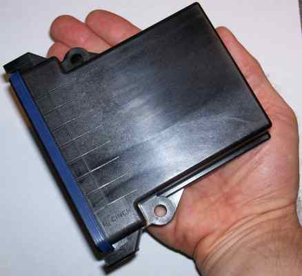
- cinchME.jpg (17.48 KiB) Viewed 1842 times
Hmmm ... I might wire a jumper to the 'main' output; that way the spares would be ... Nope. That would bypass the 'fuel' relay, and everything downstream of it would be powered when the 'main' relay comes on. Hmph.
Re: Wiring in relays for fan/water injection control etc.
Posted: Sat Oct 22, 2011 3:32 pm
by dontz125
Ok, that was easier than I thought. Presenting - the 'C' (carburetor) model, with the two 'spare' relays activated independently of the 'fuel pump' relay. The PWM option is also deleted.
Re: Wiring in relays for fan/water injection control etc.
Posted: Sat Oct 22, 2011 4:12 pm
by anonymous.shyster
Looks promising, so can it fit inside the Microsquirt enclosure? I'm guessing not since it has a huge connector on it?
Re: Wiring in relays for fan/water injection control etc.
Posted: Sat Oct 22, 2011 4:21 pm
by dontz125
There's no room for just about ANYTHING in a uS enclosure - they are VERY tight. No, this is a stand-alone (beside?) unit. The relay board you were contemplating earlier was also a stand-alone. Actually, it was almost big enough to fit the uS inside itself!

Re: Wiring in relays for fan/water injection control etc.
Posted: Sat Oct 22, 2011 4:25 pm
by anonymous.shyster
Not trying to hijack my own thread, but I am just going over what current things draw to see if it's suitable and I got to thinking about how things can be triggered etc. Here's a scenario, can someone tell me if this is possible?
Intercooler fan and pump is turned on and off depending on the intercooler (water to air) coolant temperature. If the coolant (non-glycol) gets to a temperature 7C above ambient the fan and pump are running OR if the throttle exceeds a threshold (1/2) it will also come on. The fan and pump are turned off again after another threshold has been reached, i.e temperature is now 5C above ambient. I'd like to able to do this, it does sound efficient, doesn't it?