Trigger wheel on Husaberg

This forum is for discussing ignition setup, tuning, and troubleshooting for MicroSquirt (TM)
Forum rules
Read the manual to see if your question is answered there before posting. If you have questions about MS1/Extra or MS2/Extra or other non-B&G code configuration or tuning, please post them at http://www.msextra.com The full forum rules are here: Forum Rules, be sure to read them all regularly.
Post Reply
Eszterle
MegaSquirt Newbie
Posts: 3
Joined: Sat Jan 22, 2011 12:12 pm

Trigger wheel on Husaberg

Post by Eszterle »

Hi!

After solving many problems I got stuck at the (hopefully) very last thing and don't really know how to solve this problem ... Maybe you got an idea.

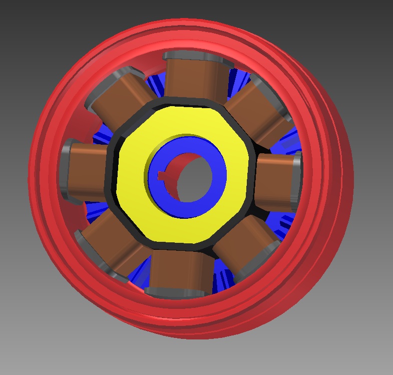
First some pics of my flywheel ...

Image
Image
Image

Then some data ...

Outer diameter of the flywheel: 105-106mm
Inner diameter of the cover: 112-113mm
Thickness of the outer metal ring: 4mm

Now how am I going to fit a trigger wheel? I was thinking about some solutions ...

1. Cutting the outer metal ring like he did it.
Problems: I would have to remove the metal trigger which is on the outside at the moment. Wouldn't be a big deal since I couldn't use it any more. But I don't know if the ignition needs the whole ring? Could I machine it? Would the teeth with 3-4mm be high enough? Also one part of the wheel hasn't got the full diameter as you can see in the picture.

2. Welding/shrinking a normal trigger wheel on the outside of the flywheel.
Problems: I just got about 6mm space so the teeth couldn't be really high. Maybe like before 3-4mm. Would that be enough?

3. Cutting a part of the outer metal ring completely down to the magnets and then weld or rather shrink (Welding isn't that good for permanent magnets?) a trigger wheel on the outside.

As you can see it's quite hard ... :( Could someone help me? :)


Best regards,
Chris
Eszterle
MegaSquirt Newbie
Posts: 3
Joined: Sat Jan 22, 2011 12:12 pm

Re: Trigger wheel on Husaberg

Post by Eszterle »

Hi!

After some work I could have found a solution ... What do you think: Could that work? (Very little space between the flywheel and the spools but we'll see ...)

I would put the sensor between the spools as far out as I can.

Some shots so you just get an idea ...

Image
Image
Image


Regards
mxrob
Helpful Squirter
Posts: 44
Joined: Thu Dec 24, 2009 5:43 pm
Location: Kentwood, MI
Contact:

Re: Trigger wheel on Husaberg

Post by mxrob »

The stock rotor looks like it could be facing a strength issue if you modified it's outer shell. Your internal toothed shell looks good. You'd have to find a way to pin it or key it in position obviously. I'm wondering if the sensor mounted between the charging coils like that would be an issue with EMF?
DR650 Dual Sport thumper µs FI success!
24c
Master Squirter
Posts: 593
Joined: Sat Feb 16, 2008 12:15 pm
Location: Chorley, Lancashire UK
Contact:

Re: Trigger wheel on Husaberg

Post by 24c »

Eszterle wrote:...Could someone help me? :)
I would get a laser cut toothed ring, maximum thickness 6mm overall including the teeth, with a thickness of 3mm and a tooth height of 3mm. I would possibly undercut the end of the flywheel slightly to make a positive stop & keep it square. You don't need to weld, as you can use engineering adhesive/retainer aka Loctite. If needed you might reduce the teeth in a lathe to true it up, but I wouldn't expect too many issues.

Next make a hole in the cover for the sensor, and as long as you have a good mounting, everything will be OK, but allow for moving the sensor closer or further from the teeth.

Good luck.
Eszterle
MegaSquirt Newbie
Posts: 3
Joined: Sat Jan 22, 2011 12:12 pm

Re: Trigger wheel on Husaberg

Post by Eszterle »

Hi!

@mxrob: Yesterday I realised that the outter shell is definately not able to be machined. Pinning it is no problem since it is pinned with the same feather key the flywheel is pinned with.

@24c: Good idea! The thing is that there's almost no space between the flywheel and the cover. Maybe 3-4mm between the outside of the flywheel and the inside of the cover ... BUT glueing it is a really nice idea! I'm facing some problems because there is just very little space between the coil-holding-metal-ring and the flywheel. I somehow made a v2 of the drawing and everything ist just like original now regarding the measurements. ;) So you can have a look.

The only solution that I see is this way actually. It would also be P&P! But there are just 1,5mm on each side between the coil-metal ring and the flywheel which leaves just 1mm thickness for the trigger-wheel. This isn't much but the trigger wheel is supported by the flywheel on the bottom and at the outside so there should almost come no forces onto the part which is holding the wheel into place. Even if it would become a problem I could machine the metal-ring so it is wider OR just glue the part with the teeth on it into place.

Red = Flywheel&magnet
Blue = Trigger wheel
Silver&copper = Coils
Black = Coil plastic ring
Yellow = Coil metal ring
Green = Part of the flywheel cover

Image
Image
Image


Regards
24c
Master Squirter
Posts: 593
Joined: Sat Feb 16, 2008 12:15 pm
Location: Chorley, Lancashire UK
Contact:

Re: Trigger wheel on Husaberg

Post by 24c »

OK, nice drawings, but I still think you can machine the outer ring for 4mm or so and glue a ring on.

However, it is tight.... so why not take the flywheel and mill/drill with a flat bottomed mill, and use a dividing head. This way you could machine a slot or teeth by drilling round indentations. My Yamaha crank does this, plus it doesn't reduce the thickness/strength due to centrifugal loads.

These are the four teeth for the GTS1000

Look at the bottom image to see the Thunderace slot pattern, which is 8 teeth with only 1/2 a slot.
So to create a missing tooth to work with B&G code, your slot would have to be a whole division between the circular holes. What I'd do, is make say 60 or whatever, (check they'll fit, 36, or 12 might be better) 8mm diameter divisions and then remove the metal between two of them to create a slot.

BTW, these are only 2.5mm deep maximum and trigger OK.

Hope this helps...I reckon it will :)

EDIT, Just read this post again, and I should say the drilled teeth are not on the same plane as my cranks, but around the flywheel cylindrical face, as in like a pushed on toothed ring, but going into the existing metal, not sitting on top of it.
Post Reply