Page 1 of 4

VR sensor board mods for uS vs AC Zener voltage clamp

Posted: Sat Dec 18, 2010 1:56 pm
by Aaron Silidker
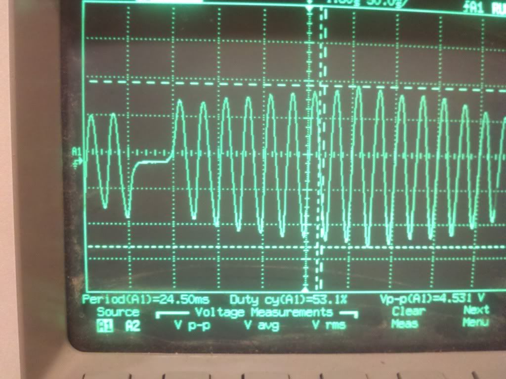
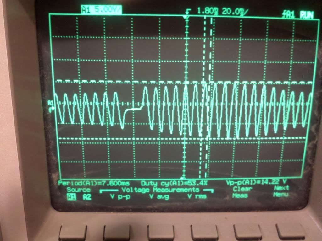
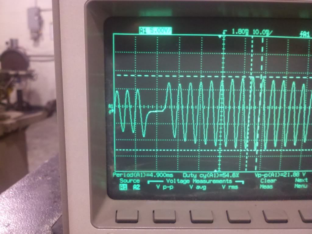
Using my bikes stock VR sensor in my conversion to EFI. Since the stock VR charges the capacitor for the stock CDI, it has very high gain. I have seen at least 200 volts from the sensor (doing some more testing with a scope tomorrow).

If I do the board mods listed on page one of this thread http://www.microsquirt.com/viewtopic.ph ... 3&start=10 as well as the upgraded firmware bruce described in page two and here http://www.microsquirt.com/viewtopic.php?f=87&t=23198 will I be okay? Or do I need to fabricate and install some sort of Zener AC clamp near the sensor to lower voltage?

Even if the two above listed uS mods work well, due to high noise from the VR circuit, would I be safer to clamp the AC voltage near the sensor?

Thanks!

Re: VR sensor board mods for uS vs AC Zener voltage clamp

Posted: Sun Dec 19, 2010 12:23 am
by 24c
Aaron Silidker wrote:Using my bikes stock VR sensor in my conversion to EFI. ...
So you are removing the stock CDI and just worried the AC spike will be too high. My only problem was my AC voltage spike wasn't high enough under cranking to trigger the VR2+ circuit, but I did play around with resistors and diodes when I had noise issues and struggling to sync.

Couldn't you just lower the voltage with an inline resistor? You should be able to scope it under cranking, plugs out (if you don't have a cranking rig), and just place resistors in line to lower it. IIRC lower than 2V p-p was the limit for VR2, but VR1 saw it easily, and that was using TachRef.exe

Re: VR sensor board mods for uS vs AC Zener voltage clamp

Posted: Sun Dec 19, 2010 6:37 am
by Peter Florance
24c wrote:
Aaron Silidker wrote:Using my bikes stock VR sensor in my conversion to EFI. ...
So you are removing the stock CDI and just worried the AC spike will be too high. My only problem was my AC voltage spike wasn't high enough under cranking to trigger the VR2+ circuit, but I did play around with resistors and diodes when I had noise issues and struggling to sync.

Couldn't you just lower the voltage with an inline resistor? You should be able to scope it under cranking, plugs out (if you don't have a cranking rig), and just place resistors in line to lower it. IIRC lower than 2V p-p was the limit for VR2, but VR1 saw it easily, and that was using TachRef.exe
I beta tested the 1st version Sequencer and mod'd the input to exactly what your MicroSquirt has and it works well with 60-2 Bosch (pretty high output. I think it will work fine if you do the Mod's that Bruce suggested

Re: VR sensor board mods for uS vs AC Zener voltage clamp

Posted: Sun Dec 19, 2010 10:30 am
by Aaron Silidker
I will be scoping the output of the VR on the lathe with the flywheel later today.

When I scoped it on the bike with the long CDI tooth, output was VERY high.

What is the 1st version sequencer? I will do a search for this also....

Re: VR sensor board mods for uS vs AC Zener voltage clamp

Posted: Sun Dec 19, 2010 11:06 am
by Aaron Silidker
Search solved the sequencer mystery for me.

When you say you modded the input to exactly what my microsquirt has what do you mean? I have an unmodified 1st gen microsquirt I bought second hand from some folks who were having major problems with the VR sensor on the stock retrofit application. They told me at the time about trying to use trim pots to get it to work, but I think this was well before Bruce came up with the board mods and the updated firmware.

Basically, if microsquirt is okay with high voltages after the mods Bruce listed then I will try to do those myself. If not, I will also use either a series resistor or a set of parallel/series zeners with a series resistor to limit current as an AC waveform voltage clamp circuit.

What do the experts think?

I will try to post a "screen" shot (aka photo) of my scoping results later on the lathe. It is pointless to test this on the bike because the bike starter will not spin the engine very quickly.

Re: VR sensor board mods for uS vs AC Zener voltage clamp

Posted: Sun Dec 19, 2010 3:57 pm
by Peter Florance
Aaron Silidker wrote:Search solved the sequencer mystery for me.

When you say you modded the input to exactly what my microsquirt has what do you mean? I have an unmodified 1st gen microsquirt I bought second hand from some folks who were having major problems with the VR sensor on the stock retrofit application. They told me at the time about trying to use trim pots to get it to work, but I think this was well before Bruce came up with the board mods and the updated firmware.

Basically, if microsquirt is okay with high voltages after the mods Bruce listed then I will try to do those myself. If not, I will also use either a series resistor or a set of parallel/series zeners with a series resistor to limit current as an AC waveform voltage clamp circuit.

What do the experts think?

I will try to post a "screen" shot (aka photo) of my scoping results later on the lathe. It is pointless to test this on the bike because the bike starter will not spin the engine very quickly.
I'm not sure what the difference between 1 and current gen AFA VR component values. I have the schematics at work (I repair them) but only see Rev 2 online. So check the current schematic and see if yours is made like that.
If you check VR sensors unloaded, they will have very large output. Much less when loaded, even with resistor as high as 10K. So check it on the lathe but check it connected to microsquirt.

Re: VR sensor board mods for uS vs AC Zener voltage clamp

Posted: Sun Dec 19, 2010 3:59 pm
by Peter Florance
I missed that you have first gen squirt. I mod'd to match v2.00

1st gen is here and does use 1K (like sequencer) for R26
http://www.microsquirt.info/microsquirtV1.00.pdf

Re: VR sensor board mods for uS vs AC Zener voltage clamp

Posted: Sun Dec 19, 2010 4:39 pm
by dontz125
Hi, Aaron.

I was a little surprised to read that your VR charges the CDI. What I'm familiar with (on a street bike) is a dedicated HV charging coil for the CDI, a lower voltage charging coil for the lights and dash, and the VR timing pickup to actually make things go bang. If you are connecting your CDI charging coil to the uS, I'm surprised you don't already have a mass of slagged parts...

Re: VR sensor board mods for uS vs AC Zener voltage clamp

Posted: Sun Dec 19, 2010 5:21 pm
by Aaron Silidker
From what I understand, because this bike is based on a model without a battery, the long tooth on the flywheel charges the CDI and the small tooth triggers it. There are actually two VR sensors that share one core.

I played around on a lathe tonight and got some absolutely ludicrous signals. The gain of the VR is out of control. At the gain I have, my peak to peak voltage...not knowing the exact gap between the flywheel and the sensor (I ran it nearly touching on the lathe) would be close to 600 volts!!! When I backprobed the connector when the bike was stock before I modified the flywheel and the bike was running, at roughly 10k RPM I saw a peak to peak of around 200+ volts. The scope I was using sucked, so the peak to peak values were wild. I will assume I have a decent sized gap when the engine is assembled. I have no good way to accurately measure the gap, so I made my teeth on my wheel the same height as the teeth on the stock flywheel. At least I know in that case I will not be hitting anything.

Anyhow, without further talk, here are my "screen shots" of the signals.

First, we have the signal at 80 RPM. Notice that the peak to peak changes and this is because I was unable to perfectly true the flywheel in the 6 jaw chuck on the lathe. The spacing changes. I think I have the polarity correct, and the signal appears extremely clean to me at a very low 80rpm which is extremely encouraging to me. Peak to peak is 4.5 volts.
Image

Here is the signal at 240 RPM. Peak to peak is 14.2 volts.
Image

Here is the signal at 400 RPM. Peak to peak is 21.8 volts.
Image

Here is what my EDM'd trigger wheel looks like
Image

I did not want to spin the wheel any faster because I actually work part time as a student adviser in a machine stop at the University of Michigan, and the kids were already questioning the safety of my "ghetto rig" as they were calling it.

How does the cleanliness of the signals appear?

I think a Zener AC clamp will be my best option here due to the extreme high gain of this sensor. Thoughts?

I wanted to play with some other combinations of probing the wires, but one of the students needed the lathe, so I had to leave it for him. I may come back next week and mess around with it some more to see if the other side has lower gains. Basically I have two VR sensors with one core, and I am unsure if they have the same gains. Hopefully the other one has a lower gain.

Re: VR sensor board mods for uS vs AC Zener voltage clamp

Posted: Sun Dec 19, 2010 5:24 pm
by Aaron Silidker
Peter Florance wrote:I missed that you have first gen squirt. I mod'd to match v2.00

1st gen is here and does use 1K (like sequencer) for R26
http://www.microsquirt.info/microsquirtV1.00.pdf

Any of you guys want to mod mine to match the second gen? As a mechanical engineer, I am really really uncomfortable working with surface mount stuff. A 6 pack of nice beer to get my all hooked up with the new style parts? :mrgreen: