Using Hall Sensors with MicroSquirt VR1 Input
Posted: Tue Nov 20, 2007 6:41 pm
There are a few applications where a hall sensor is used as the primary crank sensor. for the primary trigger into MicroSquirt, there is the opto circuit and the VR circuit. For distributor-like applications (i.e. one pulse per cylinder) the opto works well. For multitooth crankwheel arrangements the VR1 input is the preferred choice. The issue here is that the VR1 input is used for zero-crossing waveforms generated by VR sensors. The signal must pass thru zero volts to reset the built-in hysteresis circuit.
To visualize, here is a simulation of a VR sensor triggering the VR circuit:

The green smooth wave is the VR signal and the blue is the VR interface circuit triggering. You can see that the VR input signal must go thru roughly 100 millivolts to cause a trigger, and on the other side the voltage needs to pass thru roughly -50 millivolts.
The problem with using a hall sensor is that the output signal will always be above 0 volts - either near 12 volts (if biased at battery potential) or near 0.7 volts when active. There is no negative voltage to reset the hysteresis. So, what can be done?
Here is a really simple circuit I call a "Hall Sensor Offsetter", here is the schematic:
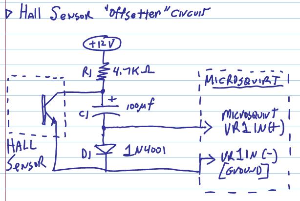
It is comprised of three components, a resistor (which may already be there for the hall sensor), a capacitor, and a diode. The capacitor in this circuit is known as a "bootstrap" capacitor, and it is used to generate an offset potential, in this case negative.
Circuit operation is simple. When the hall sensor is not conducting, the bootstrap capacitor C1 charges up thru resistor R1 ad diode D1. The voltage on the top of the capacitor is roughly battery potential when charged. The potential on the bottom of the capacitor is roughly 0.7 volts due to the diode voltage drop - this is fed into the VR1 positive input. So this potential is high enough to trigger the circuit.
When the hall sensor is conducting, the positive side of C1 is pulled to about 1 volt or so due to the transistor turning on (this is the transistor VCE value). In this case the diode D1 is not conducting so it is not in the picture. But, there is still a charge on the bootstrap capacitor acting like a battery. So the potential on the bottom terminal of the capacitor is equal to 1 volt (VCE) minus 11.3 volts (charge on the cap) to give roughly -10.3 or so volts. This is a negative voltage, enough to trip the hysteresis circuit.
Here is a simulation of the circuit:
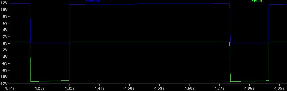
The blue waveform is the voltage on the collector of the hall sensor, and the green is the negative bootstrap capacitor (to VR1+). The voltage translation or offset is apparent on the green trace, enough to trigger the VR1 input easily. Also, there is no phase shift, just a voltage translation which is very important for accurate timing.
Finally, this circuit is for the VR1 input. The VR2 input in MicroSquirt, used most often for cam sync, is already biased to trigger at a higher value (roughly 1.8V) so it is ready for a hall sensor.
- Bruce
To visualize, here is a simulation of a VR sensor triggering the VR circuit:
The green smooth wave is the VR signal and the blue is the VR interface circuit triggering. You can see that the VR input signal must go thru roughly 100 millivolts to cause a trigger, and on the other side the voltage needs to pass thru roughly -50 millivolts.
The problem with using a hall sensor is that the output signal will always be above 0 volts - either near 12 volts (if biased at battery potential) or near 0.7 volts when active. There is no negative voltage to reset the hysteresis. So, what can be done?
Here is a really simple circuit I call a "Hall Sensor Offsetter", here is the schematic:
It is comprised of three components, a resistor (which may already be there for the hall sensor), a capacitor, and a diode. The capacitor in this circuit is known as a "bootstrap" capacitor, and it is used to generate an offset potential, in this case negative.
Circuit operation is simple. When the hall sensor is not conducting, the bootstrap capacitor C1 charges up thru resistor R1 ad diode D1. The voltage on the top of the capacitor is roughly battery potential when charged. The potential on the bottom of the capacitor is roughly 0.7 volts due to the diode voltage drop - this is fed into the VR1 positive input. So this potential is high enough to trigger the circuit.
When the hall sensor is conducting, the positive side of C1 is pulled to about 1 volt or so due to the transistor turning on (this is the transistor VCE value). In this case the diode D1 is not conducting so it is not in the picture. But, there is still a charge on the bootstrap capacitor acting like a battery. So the potential on the bottom terminal of the capacitor is equal to 1 volt (VCE) minus 11.3 volts (charge on the cap) to give roughly -10.3 or so volts. This is a negative voltage, enough to trip the hysteresis circuit.
Here is a simulation of the circuit:
The blue waveform is the voltage on the collector of the hall sensor, and the green is the negative bootstrap capacitor (to VR1+). The voltage translation or offset is apparent on the green trace, enough to trigger the VR1 input easily. Also, there is no phase shift, just a voltage translation which is very important for accurate timing.
Finally, this circuit is for the VR1 input. The VR2 input in MicroSquirt, used most often for cam sync, is already biased to trigger at a higher value (roughly 1.8V) so it is ready for a hall sensor.
- Bruce