Page 2 of 4
Re: VR sensor board mods for uS vs AC Zener voltage clamp
Posted: Sun Dec 19, 2010 5:59 pm
by dontz125
600v p-p from a VR?! That's insane!

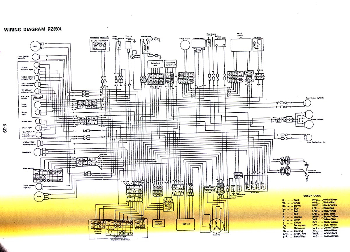
Do you have a wiring diagram for the bike? Here's a US '84 RZ350 -
http://www.angelfire.com/hi3/smokeonthewater/wirerz.jpg
It's not the best, but the magneto is down at the bottom. You can see there's the HV CDI charging coil (3 wires), the LV 3-phase lighting coil (3 wires going to the voltage regulator/rectifier, + the neutral switch), and the 2 wires of the VR pickup.
I find it difficult to rwpa my damaged brain around a VR pickup putting out that kind of juice...

Re: VR sensor board mods for uS vs AC Zener voltage clamp
Posted: Sun Dec 19, 2010 6:53 pm
by Bruce Bowling
You can use the VR input with the VR sensor. You may want to add a series resistance of, say 10K or so, put this in the VR+ line.
Do not modify any of the SMT components on the microsquirt, just feed in the VR with the series resistance.
As a datapoint, I have put in a 480 volt p-p sinewave into the microsquirt VR circuit (60 Hz) for 30 hours straight as a hipot test. You will be fine.
- Bruce
Re: VR sensor board mods for uS vs AC Zener voltage clamp
Posted: Sun Dec 19, 2010 8:31 pm
by Aaron Silidker
Bruce Bowling wrote:You can use the VR input with the VR sensor. You may want to add a series resistance of, say 10K or so, put this in the VR+ line.
Do not modify any of the SMT components on the microsquirt, just feed in the VR with the series resistance.
As a datapoint, I have put in a 480 volt p-p sinewave into the microsquirt VR circuit (60 Hz) for 30 hours straight as a hipot test. You will be fine.
- Bruce
Thank you for the reply Bruce.
No need to perform the mod as listed in this thread
http://www.microsquirt.com/viewtopic.php?f=89&t=23063 ?
I have a gen 1 board, just like the one pictured.
Also, no need to an AC Zener clamp regardless of this mod?
What wattage resistor would you recommend? What is the main purpose of the resistor in this case as you have recommended? To lower voltage, lower current, or both?
Finally, how does the general shape of my signal appear to you? Is it very clean, or typical?
THANKS!
Re: VR sensor board mods for uS vs AC Zener voltage clamp
Posted: Mon Dec 20, 2010 12:29 am
by 24c
Aaron, you been busy from all your posts. Voltages do seem high vs rpm compared to say my bikes, so you must have a high gain sensor, and I have seen Bruce's post.
I used some small diameter resistors, approx 3mm diameter (electrical isn't my area), placed them inline, and they reduced the p-p voltage.
Aaron Silidker wrote:...not knowing the exact gap between the flywheel and the sensor (I ran it nearly touching on the lathe) would be close to 600 volts!!! When I backprobed the connector when the bike was stock before I modified the flywheel and the bike was running, at roughly 10k RPM I saw a peak to peak of around 200+ volts. The scope I was using sucked, so the peak to peak values were wild. I will assume I have a decent sized gap when the engine is assembled. I have no good way to accurately measure the gap, so I made my teeth on my wheel the same height as the teeth on the stock flywheel. At least I know in that case I will not be hitting anything....
I don't know if you are aware of this, but you can also reduce the p-p voltages by increasing the air gap.
Aaron Silidker wrote:Finally, how does the general shape of my signal appear to you? Is it very clean, or typical?
Looks clean to me as a raw VR trace, typical shape... as you'd expect.
Re: VR sensor board mods for uS vs AC Zener voltage clamp
Posted: Mon Dec 20, 2010 3:56 am
by Peter Florance
24c wrote:=
I don't know if you are aware of this, but you can also reduce the p-p voltages by increasing the air gap.
+1
Also you reduce the chance of distortion at the missing tooth position
Re: VR sensor board mods for uS vs AC Zener voltage clamp
Posted: Mon Dec 20, 2010 7:49 am
by Aaron Silidker
Peter Florance wrote:24c wrote:=
I don't know if you are aware of this, but you can also reduce the p-p voltages by increasing the air gap.
+1
Also you reduce the chance of distortion at the missing tooth position
Unfortunately, due to my resistance to modify the magnesium flywheel cover that the stock VR sensor is mounted in, I am stuck where it is. My wheel is just about as low profile as possible without the risk of it flying apart thanks to 10k RPM rev limit. The flywheel is machined as small as I can without going through the housing. This is as big of a gap as I can have.
That being said, I am unsure what the actual gap is inside the engine. I have tested it with a tight gap as a worse case scenario. I have no good way to measure the gap in the assembled engine.
I do have some smaller diameter flywheels I will modify at a later date if this project works as planned. The reason I did not modify one of those at the moment is because they are expensive.
I am quite happy with the shape and cleanliness of the signal I have, but a little bit scared of the voltage. If something as "crude" as a resistor in series will be fine, then I will just do that, it is easy.
Now, on to the next question...where is a good place to get coax cable that isn't insanely large like home video cable?
Re: VR sensor board mods for uS vs AC Zener voltage clamp
Posted: Mon Dec 20, 2010 8:14 am
by Peter Florance
Just use some series resistance as Bruce recommended.
Re: VR sensor board mods for uS vs AC Zener voltage clamp
Posted: Mon Dec 20, 2010 8:28 am
by Aaron Silidker
Peter Florance wrote:Just use some series resistance as Bruce recommended.
Excellent...do I need a specific wattage or no worries as the current will be low with the resistance?
Re: VR sensor board mods for uS vs AC Zener voltage clamp
Posted: Mon Dec 20, 2010 8:39 am
by Peter Florance
Aaron Silidker wrote:Peter Florance wrote:Just use some series resistance as Bruce recommended.
Excellent...do I need a specific wattage or no worries as the current will be low with the resistance?
1/2watt might not be a bad idea but 1/4 watt would probably work
Re: VR sensor board mods for uS vs AC Zener voltage clamp
Posted: Mon Dec 20, 2010 9:32 am
by Aaron Silidker
Peter Florance wrote:Aaron Silidker wrote:Peter Florance wrote:Just use some series resistance as Bruce recommended.
Excellent...do I need a specific wattage or no worries as the current will be low with the resistance?
1/2watt might not be a bad idea but 1/4 watt would probably work
Sounds good. Both cheap, and easy!

Assume this only goes on the VR+ side..or else my total resistance would be 20k not 10k correct?
Now, how can I determine the voltage drop across this guy at each RPM? I don't know what kind of current I have coming from the VR so how do I see what type of voltage drop this will give me without measuring it with the scope again? I will likely scope it anyhow, but just for my own knowledge, is there a good way to calculate this.
I had one EECS for non EECS engineers class in school, but that was about 5 years ago and I haven't touched the subject since then so the knowledge is long gone.