Hi there
Im using a microsquirt v3 on a 97ish Husqy TC-610 and I'm having trouble getting an ignition input signal
Im using the factory ign pick up that is integrated into the stator that would normally trigger the CDI unit.
Im not sure if the microsquirt can interpret the signal correctly?
Can anyone confirm that it will or wont?
Motorcycle Ign pickup
Forum rules
Read the manual to see if your question is answered there before posting. If you have questions about MS1/Extra or MS2/Extra or other non-B&G code configuration or tuning, please post them at http://www.msextra.com The full forum rules are here: Forum Rules, be sure to read them all regularly.
Read the manual to see if your question is answered there before posting. If you have questions about MS1/Extra or MS2/Extra or other non-B&G code configuration or tuning, please post them at http://www.msextra.com The full forum rules are here: Forum Rules, be sure to read them all regularly.
Motorcycle Ign pickup
- Attachments
-
- photo.JPG
- ign pickup scope capture
- (192.86 KiB) Not downloaded yet
Re: Motorcycle Ign pickup
A picture of the bike's rotor would help. Does the bike's rotor have a tooth pattern that the Microsquirt can recognize? Usually people go with a "missing tooth" configuration.
For example: I'm working on a Suzuki GSF400. It doesn't use the rotor/stator end of the crankshaft for its tooth pattern. Instead it uses a trigger wheel mounted on the other end of the crankshaft (along with the starter clutch). In the bike's original configuration this trigger wheel had 6 teeth (five short teeth and 1 long tooth) which would not work with the Microsquirt. I cut off the long tooth to make it into a "6-1" wheel which the Microsquirt can recognize.
I'm using the bike's stock sensor pickup and it works fine all the way up to 13,500 rpm.
Re: Motorcycle Ign pickup
Ill whip the rotor off over the weekend and takes some pics
I was hoping that one ignition input would be enough to trigger the microsquirt.
I was hoping that one ignition input would be enough to trigger the microsquirt.
Re: Motorcycle Ign pickup
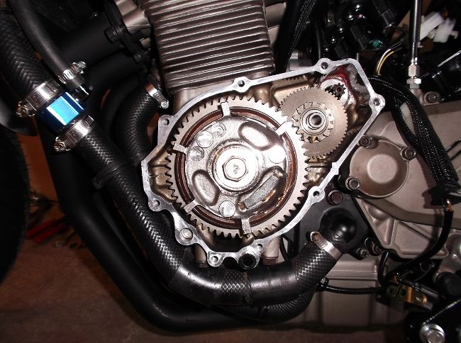
Here are pics of the rotor and stator
- Attachments
-
- rotor.jpg (18.08 KiB) Viewed 3709 times
-
- stator.jpg (23.11 KiB) Viewed 3709 times
Re: Motorcycle Ign pickup
Are you trying to set up the bike "fuel-only" (no ignition control)? If that's the case then all you need is a tachometer type signal.
On my first motorcycle project (a Kawasaki EX-250) I did a fuel-only setup. I left the original rotor/stator and pulse sensor in place and the original CDI too. Then I just used a tachometer signal from the CDI to trigger the microsquirt. The signal I used was the CDI box's negative (ground) signal to the bike's number 1 coil.
On my first motorcycle project (a Kawasaki EX-250) I did a fuel-only setup. I left the original rotor/stator and pulse sensor in place and the original CDI too. Then I just used a tachometer signal from the CDI to trigger the microsquirt. The signal I used was the CDI box's negative (ground) signal to the bike's number 1 coil.
Re: Motorcycle Ign pickup
But if you're trying to control both fuel and ignition with the Microsquirt you will need a tooth pattern that the Microsquirt is programmed to interpret.
I can see from your pictures that your bike's "pickup" (the pulse generating sensor, more properly known as a "variable reluctance sensor") is mounted inside the perimeter of the rotor, on top of the generator stator. Wow, that's a totally different way of doing it compared to every American and Japanese system I've ever seen. The American and Japanese engineers always mount the sensor outside (at the perimeter) of whatever is acting as the signal wheel.
In the pictures I can see that your bike's "pickup" faces inward, toward the crankshaft. It obviously reads (senses) a pattern of small "teeth" that are on the outside of the rotor's mounting hub. But your picture of the rotor doesn't give me a side-on view of this area (the rotor's hub) so I cannot see the tooth pattern.
If you could take a few more pictures of the rotor's hub, enough so I can piece together a complete 360 degree view. Then we can talk about what the original pulse pattern is and whether it can be modified to a pattern that the Microsquirt can use.
Re: Motorcycle Ign pickup
i want to run both fuel and ign
no sorry thats a bad pic, the vr sensor is pointing out away from the crank shaft
There are two rows of magnets inside the rotor, the set further away from the camera are the ones that trigger the ign events and charge the 200v part of the stator (currently not connected).
This bike is a single cylinder four stroke
can i use one trigger event (pulse) from the oem system to trigger the microsquirt?
Re: Motorcycle Ign pickup
What you're saying is a bit confusing. Here's why: A VR sensor is a magnet, it doesn't need another magnet to generate a pulse, all it needs is for a piece of ferrous metal (known as a "trigger wheel tooth") to pass by in close proximity to it.no sorry thats a bad pic, the vr sensor is pointing out away from the crank shaft
There are two rows of magnets inside the rotor, the set further away from the camera are the ones that trigger the ign events and charge the 200v part of the stator
So something is weird/wrong in this interpretation of the situation. Either the sensor isn't a standard VR type of sensor or you've misidentified the situation (i.e. maybe the inner row on the rotor aren't magnets, just areas of non-ferrous metal occasionally interrupted by little bits of ferrous metal, which would generate pulses on a normal VR sensor). Is there a pattern that you can see in the sections of the inner rotor? Or is it just a continuous, uninterrupted circle of "magnets".
How many wires (total count) are there coming out of the rotor/stator/pulse generator housing? If your bike has just a standard 3-phase AC generator + a standard VR sensor there should be 5 total wires (3 wires for the AC phases and 2 wires for the VR sensor).
Is that all your rotor does, just one pulse for every crankshaft rotation? I don't think you can control ignition with it. I think a single crankshaft pulse per crankshaft rotation can only do a "fuel-only" setupcan i use one trigger event (pulse) from the oem system to trigger the microsquirt?
A single pulse per crankshaft rotation is enough information for the microsquirt to deliver fuel, that's what I have done on my Kawasaki EX-250.
Re: Motorcycle Ign pickup
From a 10-sec Google search, this is a pure-dirt bike, with no lights or signals, running a high-voltage AC CDI box. These are very hard to convert to EFI, because there's no charging system to power the various components. A pure-loss system with just a 12v battery can be made to work, but this is very time-limited. Great for track pounding, but don't take it into the trails or dunes ...
Depending on the actual triggering method, I'm not sure you'd be able to drive the stock CDI box. It may be a case of simply ripping the entire ignition system off along with the carb(s).
Depending on the actual triggering method, I'm not sure you'd be able to drive the stock CDI box. It may be a case of simply ripping the entire ignition system off along with the carb(s).

Re: Motorcycle Ign pickup
i dug a little more deeper and the stock pickup is a coil wound around a soft iron structure, there is no magnet in it, hence why the signal is odd looking., and there are def two magnets side by side inside the rotor.
looks like i will need to mount a trigger wheel and pick up somewhere on the crank.
i bought this bike with zero electrics on it, everything electrical had been remved so perfect candidate for my first micro squirt project.
this bike has a single phase 12 volt ac stator, i have fitted a very small SLA battery and Reg/rectifier to power it, hopefully the power wont be too dirty to upset the micro squirt if not i can replace the stator with a 3 phase unit.
thanks for your help