Hi,
I've got microsquirt installed on my mk1 Golf 16VG60 conversion but the rev counter doesn't work.
Can anyone help me with what signal I need for the original clocks?
This link details how to make them work with Megasquirt
http://www.clubgti.com/showthread.php?1 ... ev-counter
but I was wondering if it's the same approach or if the tacho output signal on pin 35 can be used somehow?
Any help appreciated
Thanks, Mike
Rev counter signal for mk1 Golf clocks
Forum rules
Read the manual to see if your question is answered there before posting. If you have questions about MS1/Extra or MS2/Extra or other non-B&G code configuration or tuning, please post them at http://www.msextra.com The full forum rules are here: Forum Rules, be sure to read them all regularly.
Read the manual to see if your question is answered there before posting. If you have questions about MS1/Extra or MS2/Extra or other non-B&G code configuration or tuning, please post them at http://www.msextra.com The full forum rules are here: Forum Rules, be sure to read them all regularly.
-
Matt Cramer
- Super Squirter
- Posts: 910
- Joined: Sat Jul 03, 2004 11:35 am
Re: Rev counter signal for mk1 Golf clocks
What exactly are you using for an ignition on this car?
Matt Cramer at DIY Autotune

Re: Rev counter signal for mk1 Golf clocks
Hi, sorry for the delay in posting back - was wanting to get a pic.
Ignition is fairly standard for the VW KR or 9a engine with coil, distributor and spark plugs rather than coil packs (I assume this is what you meant?)
Pic below of the coil if that helps?
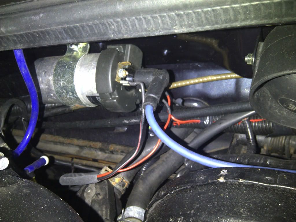
Thanks
Ignition is fairly standard for the VW KR or 9a engine with coil, distributor and spark plugs rather than coil packs (I assume this is what you meant?)
Pic below of the coil if that helps?
Thanks
-
Matt Cramer
- Super Squirter
- Posts: 910
- Joined: Sat Jul 03, 2004 11:35 am
Re: Rev counter signal for mk1 Golf clocks
So how is the rev counter wired up now, and how was it wired up before you put the MicroSquirt on it?
Matt Cramer at DIY Autotune
Re: Rev counter signal for mk1 Golf clocks
I guess a bit more background would help with this problem, so here goes....
I didn't do the microsquirt installation, so I'm going on the assumption that it's not connected to the rev counter yet. I'd seen posts on club gti such as the link above where people have used a diode circuit on the megasquirt spark A and B cables, then connected this to the red/black signal wire that feeds the rev counter in the mk1 gti clocks. I'm not exactly sure where this wire gets its signal from but that's a good line of questioning. I'll try and get hold of the circuit diagrams for the original system.
What I was hoping when I originally posted was that someone would be familiar with the megasquirt circuit mod and be able to tell me if microsquirt is the same or similar, or if I could take a feed from somewhere to get a usable rev counter signal?
I don't know the details of the mk1 clocks but was hoping that someone might know from the diode circuit what was needed and how that could be achieved from the microsquirt.
It's going back to the place that did the installation soon for some fettling, but they were looking at a solution of somehow grafting an aftermarket revcounter mechanism into my mk1 clocks, which I want to avoid if possible.
So..... is there a way, or could you suggest what steps I need to go through to find the signal I'm after?
Thanks, Mike
-
Matt Cramer
- Super Squirter
- Posts: 910
- Joined: Sat Jul 03, 2004 11:35 am
Re: Rev counter signal for mk1 Golf clocks
There's a good chance you can just leave the tach wired up the same way it's wired now; if it triggered off the coil then, it can still trigger off the coil, since you're not changing the number of coils or anything.
Matt Cramer at DIY Autotune
Re: Rev counter signal for mk1 Golf clocks
Thanks Matt, I think you are absolutely right. I wasn't familiar with wasted spark and how it works, so didn't realise that the diode arrangement isn't necessary for my setup. I think the original wiring takes a feed off the -ve side of the coil so that should still be the case.
EDIT: this was the exact problem. Once the red/black wire was traced back to the loom for the clocks and a new feed from the coil grafted in it works perfectly.
Thanks again for the help (and your patience!)
EDIT: this was the exact problem. Once the red/black wire was traced back to the loom for the clocks and a new feed from the coil grafted in it works perfectly.
Thanks again for the help (and your patience!)