So, according to this there are jumpers, OPTOIN, TACHSELECT, TSEL, OPTOOUT, SJ10, IGN, XG1 and XG2.V3.0 main board:
DB37 pin #36 to the SAW pin (#3) on the ignition module
DB37 pin #24 to the PIP pin (#1) on the ignition module
On the V3.0 main board:
use the 'Hall sensor circuit' (step #50.a in the assembly guide) - jumper D1 and D2,
jumper OPTOIN to TACHSELECT on the bottom side of the PCB, near the DB37 connector, opposite the heat sink,
jumper TSEL to OPTOOUT on the bottom side of the PCB, near the center.
jumper JS10 to IGN (this uses the processor port for the SAW signal directly),
jumper XG1 to XG2 on the bottom side of the PCB, near the 40 pin socket
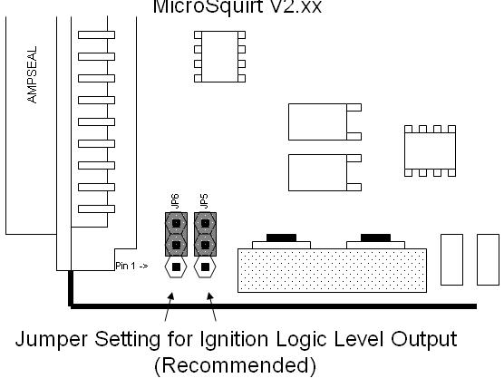
My board only has JP5, JP6 and three jumpers without and distinct markings. Can someone explain this to me? Is the documentation I'm looking at out of date?