Does anyone have a diaram for connecting a Microsquirt harness to a Jimstim?
Please help.
Connecting Jimstim to Microsquirt
Forum rules
Read the manual to see if your question is answered there before posting. If you have questions about MS1/Extra or MS2/Extra or other non-B&G code configuration or tuning, please post them at http://www.msextra.com The full forum rules are here: Forum Rules, be sure to read them all regularly.
Read the manual to see if your question is answered there before posting. If you have questions about MS1/Extra or MS2/Extra or other non-B&G code configuration or tuning, please post them at http://www.msextra.com The full forum rules are here: Forum Rules, be sure to read them all regularly.
-
racingmini_mtl
- Helpful Squirter
- Posts: 61
- Joined: Sun May 02, 2004 5:51 am
- Location: Montreal, Canada
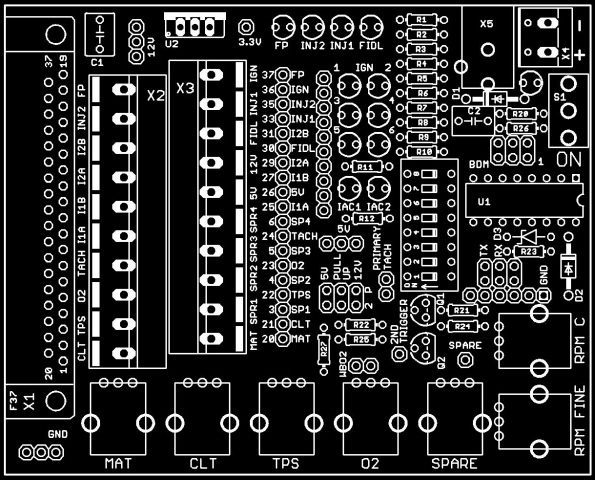
I don't have a diagram per se and I don't have a Microsquirt but if you have a look at this: http://www.microsquirt.info/schm8.gif and this: http://jbperf.com/JimStim/jim_stim_v1_3_silkscreen.jpg, you should be able to see what goes where. Have a look at the signal name besides each screw terminal position on the JimStim picture (which is the same as what's on your board) and match them with the Microsquirt signal on the Ampseal connector.
There are a few signals that will need to be connected differently. VR2IN+, if used, will need to be connected directly to the second pin header on the JimStim and IGNOUT2, if used, will need to be connected directly to one of the ign LED on the JimStim.
Hopefully this will be sufficient to get you going.
Jean
Jimstim to Microsquirt connection
I gUess I need clarification on what the pins on the Jimstim marked I1A, I1B, I2A, I2B, FP, SPR1, SPR2, SPR3, SPR4
And also what to do with all the grounds.
And also what to do with all the grounds.
-
racingmini_mtl
- Helpful Squirter
- Posts: 61
- Joined: Sun May 02, 2004 5:51 am
- Location: Montreal, Canada
I1A, I1B, I2A, I2B are the IAC stepper motor pins used on the V3.0 board with an MS2. On the JimStim, these are actually just connected on the DB37, screw terminals, and the 19-pin header in the middle of the board. So you can basically ignore them. SPR1-4 are the spare pin on the V3.0 board and you can similarly ignore them. FP is the fuel pump output and it is connected to the FP LED and it corresponds to pin 8 on the Microsquirt Ampseal connector.
You only need to connect a single ground to the JimStim ground because there won't be much current going through. For this you can either use the JimStim ground pin header (just besides the DB37, bottom left of the pic) or the power screw terminal - side (top right of the pic, X4).
Jean
You only need to connect a single ground to the JimStim ground because there won't be much current going through. For this you can either use the JimStim ground pin header (just besides the DB37, bottom left of the pic) or the power screw terminal - side (top right of the pic, X4).
Jean
-
racingmini_mtl
- Helpful Squirter
- Posts: 61
- Joined: Sun May 02, 2004 5:51 am
- Location: Montreal, Canada
MAT = Manifold Air Temperature.
The only wheel patterns available on the JimStim are the ones listed here:http://jbperf.com/JimStim/JimStim_v1_3_ ... .html#mode.
By the way, is that a custom setup or are you using a standard setup and if so, what is it from?
Jean
The only wheel patterns available on the JimStim are the ones listed here:http://jbperf.com/JimStim/JimStim_v1_3_ ... .html#mode.
By the way, is that a custom setup or are you using a standard setup and if so, what is it from?
Jean
We just downloaded the latest firmware and now the Microsquirt doesn't communicate with the JimStim at all. Any suggestions? We have two Microsuirts, one we just got from Bruce two days ago (#2) and one we got from DIY Autotune a couple of weeks ago (#1). The JimStim would communicate with the older one (#1) except on the O2 and ignition channel, and the newer one (#2) not at all. So we made them both the same and now neither one communicates at all. Consistent if nothing else. I must be missing a key element in the interpretation of the process.
Thank you
Thank you